

描述
A tripod turnstile system is more than just a gate; it is an integrated system comprising hardware, electronic components, and software designed to control, record, and report every instance of pedestrian entry and exit. When components are properly selected and integrated, the system operates seamlessly in the background—managing access rights, collecting attendance data, and blocking unauthorized entry without the need for manual intervention.
Improper component selection or poor integration quality can lead to congestion, frequent false alarms, and maintenance challenges. This guide provides an in-depth look at the various aspects of a complete tripod turnstile system, helping you deploy it with confidence.
Five Core Components of a Tripod Turnstile System
Understanding the functions and quality standards of each component is essential for making informed purchasing decisions.
1. Housing (Main Structure)
The housing serves as the structural shell of the entire tripod turnstile system. Commercial-grade housings are constructed from SUS304 stainless steel, with a minimum wall thickness of 1.0mm for the body and 1.2mm for the top cover. Full-welding techniques eliminate seam gaps, ensuring structural stability and maintaining the Ingress Protection (IP) rating even after years of heavy use; conversely, insufficient wall thickness or modular assembly methods can compromise performance in these areas.
2. Mechanical Core
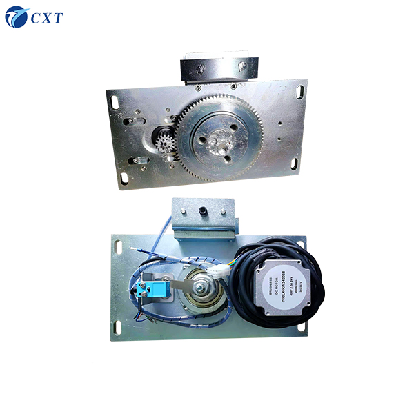
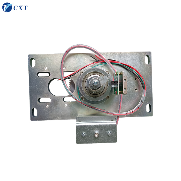
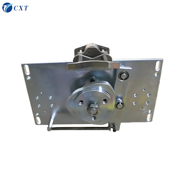
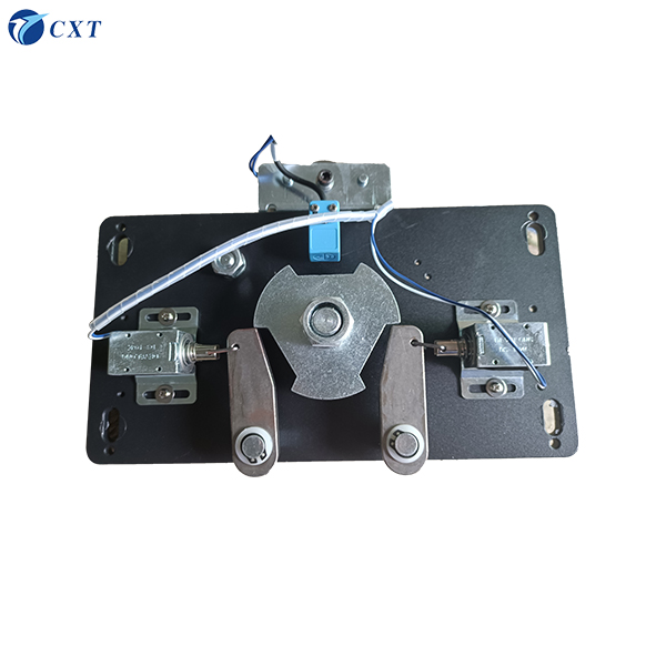
The core is the system’s central component, housing the drive shaft, gears, springs, and either electromagnets (for semi-automatic models) or brushless DC motors (for fully automatic models). The core controls the rotation of the turnstile arms. For systems handling a daily throughput of 500 to 1,000 passages, the durability of the core is not a minor detail but a critical factor determining long-term costs. Turboo’s commercial-grade cores are designed for a lifespan exceeding 5 million arm rotations.
3. Control Board (PCB)
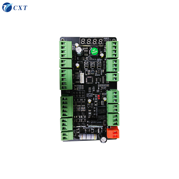
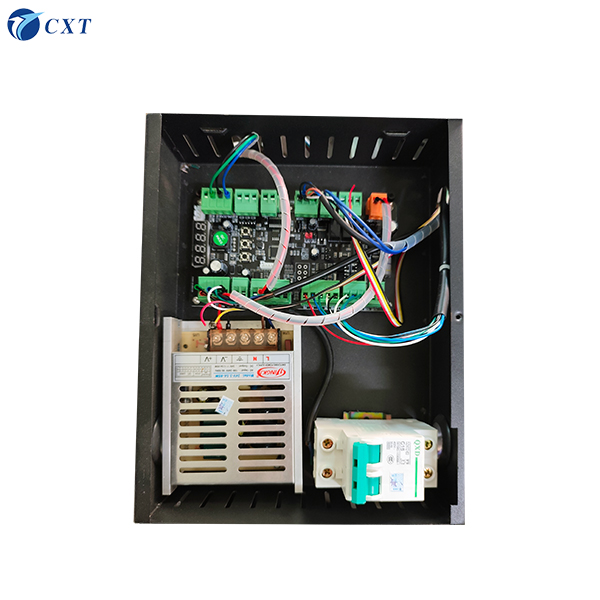
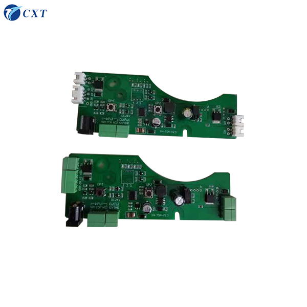
The control board serves as the intelligent heart of the system. It is responsible for receiving access signals from card readers or identification devices, managing the timing of arm release, executing anti-tailgating and anti-passback logic, controlling LED status indicators, handling the automatic arm-drop function during power outages (safety mode), and outputting access data to the connected software platform via an RS485 interface. Control board features to verify before purchase include:
Dry contact input (compatible with any third-party card reader)
RS485 bidirectional communication (essential for real-time data logging)
Wiegand input support (compatible with legacy systems)
Configurable reset timer (1–10 seconds)
Memory mode switch (controls credential verification logic for multiple passages)
External alarm output terminals
4. Rotating Arms
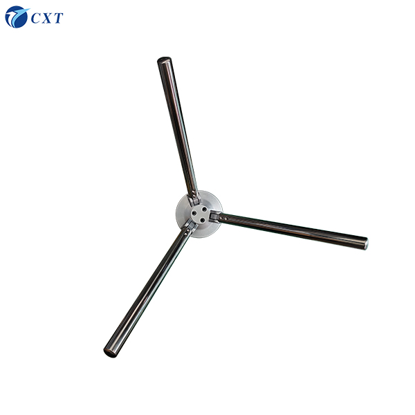
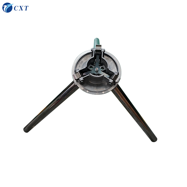
Three stainless steel arms (SUS201 or SUS304 material) evenly spaced at 120-degree angles. The standard arm length is 500 mm. The rotating arms form a physical barrier; they must be rigid enough to withstand forced entry yet have a smooth surface for easy pushing by users, while also being precisely balanced to ensure they always reset to the correct locked position.
5. Card Reader and Credential Interface
Technically, the credential reader is a standalone device, yet it is an integral part of the tripod turnstile system. The reader is responsible for verifying credentials and sending signals to the control board. The type of reader determines which credentials the system accepts, thereby defining the user demographic it can serve. Turboo’s systems support various input methods, including IC/ID cards, NFC, QR codes, barcodes, fingerprints, facial recognition, body temperature detection, and coins/tokens.
For a comprehensive overview of Turboo’s turnstile product range, please visit the tripod turnstile product page.
How a Complete Tripod Turnstile System Works: A Step-by-Step Breakdown
The following outlines the complete operational process—from card swiping/credential presentation to data output:
Step 1 — Presenting Credentials
A pedestrian presents their credential to the installed card reader. The card reader verifies the credential information against a local database or a connected server.
Step 2 — Signal Output
The card reader sends a dry-contact relay closure signal or an RS485 command to the turnstile control board. The signal duration must be one second or less; if the signal lasts too long, the turnstile will remain unlocked after the arm completes a rotation, creating a security risk.
Step 3 — Arm Release or Drive
The control board activates the solenoid release mechanism (semi-automatic mode) or triggers the brushless motor (fully automatic mode), allowing the arm to rotate freely.
Step 4 — Passage
Authorized personnel push the arm to pass through (semi-automatic mode), or the arm rotates automatically (fully automatic mode). The arm rotates 120°, allowing one person to pass.
Step 5 — Automatic Reset
The turnstile immediately returns to the locked state after a person passes; if no one passes, it locks again after the preset reset timeout expires. The system is then ready to process the next passage request.
Step 6 — Event Logging
The control board transmits passage events (including credential ID, timestamp, direction of passage, and lane ID) via the RS485 interface to the connected access control or time and attendance software. This data is used to generate reports, trigger alarms, and update dashboard information in real time.


评价
目前还没有评价